
Design Of Bell Crank Lever Diagram
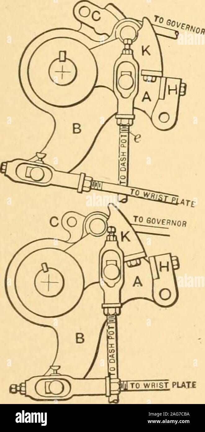
Designing of the bell crank lever involves considering the various forces acting on it. Due to this the bell crank is subject to bending and crushing stress. 2.2.1 Determination of forces acting on it A bell crank lever in which the effort and load arm are at an angle to each other. Complete the work. The bell crank lever is an apparatus shown in Figure-1 which is used to verify the law of moments. The bell crank apparatus is capable for changing the direction of rotation. It is a type of crank which changes motion around a 90 degree angle. The free body diagram of the bell crank apparatus is shown in Figure-2.

Suspension Bell Crank


Design Of Bell Crank Lever Action
Parametric design charts are proposed for the central-lever steering linkage, generated for simplified reference configuration mechanisms, the geometry of which is defined by only four parameters. This highlights the fact, yet not generally acknowledged, that the steering law ensured by a mechanism with adjacent central joints (known as bell crank mechanism), can be identically generated by a triple central joint variant of the same. Particular configurations are identified in which the length of the central lever does not affect the wheel-to-wheel transmission function of the mechanism, permitting a simplified synthesis for the cases in which the maximum stroke of the input member is imposed as a design specification.